NaoDec Build — Step 2: NaoDec Structure Set-Up
Revision: 1.1 Date: 2026-07-14 Status: 2.1 (panel build) is outlined pending materials; 2.2 (panel installation) is now specified per the author's decisions — hinged pairs, erection order, and the all-edges-hinged rule. Residual unknowns (door mechanism, hinge spec, bracing) are in Open Items.
Rev 1.1 — §2.2 Panel Installation filled in per decisions 6+7 and 9 in
NaoDec_Build_Pending_Decisions.html: every lettered edge carries 2 hinges (ground edges none), panels pre-build into 5 hinged pairs + the door, erection runs lower section → upper section → ceiling pair. Face references aligned to the marking-guide renumbering (Face N=fN).Rev 1.0 — Initial outline (2.1 panel build; 2.2 was undefined).
Purpose
Step 2 builds and erects the NaoDec frame itself on top of the Step 1 platform: the 11 built pentagon panels of a regular dodecahedron, joined edge-to-edge by hinges.
Quick Reference
| Fact | Value |
|---|---|
| Shape | Regular dodecahedron — 20 vertices, 30 edges, 12 pentagon faces |
| Faces built | 11 of 12 — f12 (bottom) intentionally unbuilt as the entry opening |
| Panel construction | Wooden frame + stretched fabric |
| Panel grouping | 5 hinged pairs + 1 single panel (the door f11) |
| Pair hinge joints | M (f7-f8) · O (f9-f10) · R (f2-f6) · T (f3-f4) · U (f1-f5) |
| Joint fastening | 2 hinges per lettered edge — all 25 joints (50 hinges); the 5 ground edges get none |
| Door face | f11 |
| Top / ceiling face | f1 |
| Dihedral angle | ≈ 116.57° between adjacent faces (regular dodecahedron) |
| Joint marking | Matching letters join (A–Z, no W) — 25 lettered joints, per the marking guides |
| Edges resting on the platform | 5 unlettered edges, on faces f7–f11 |
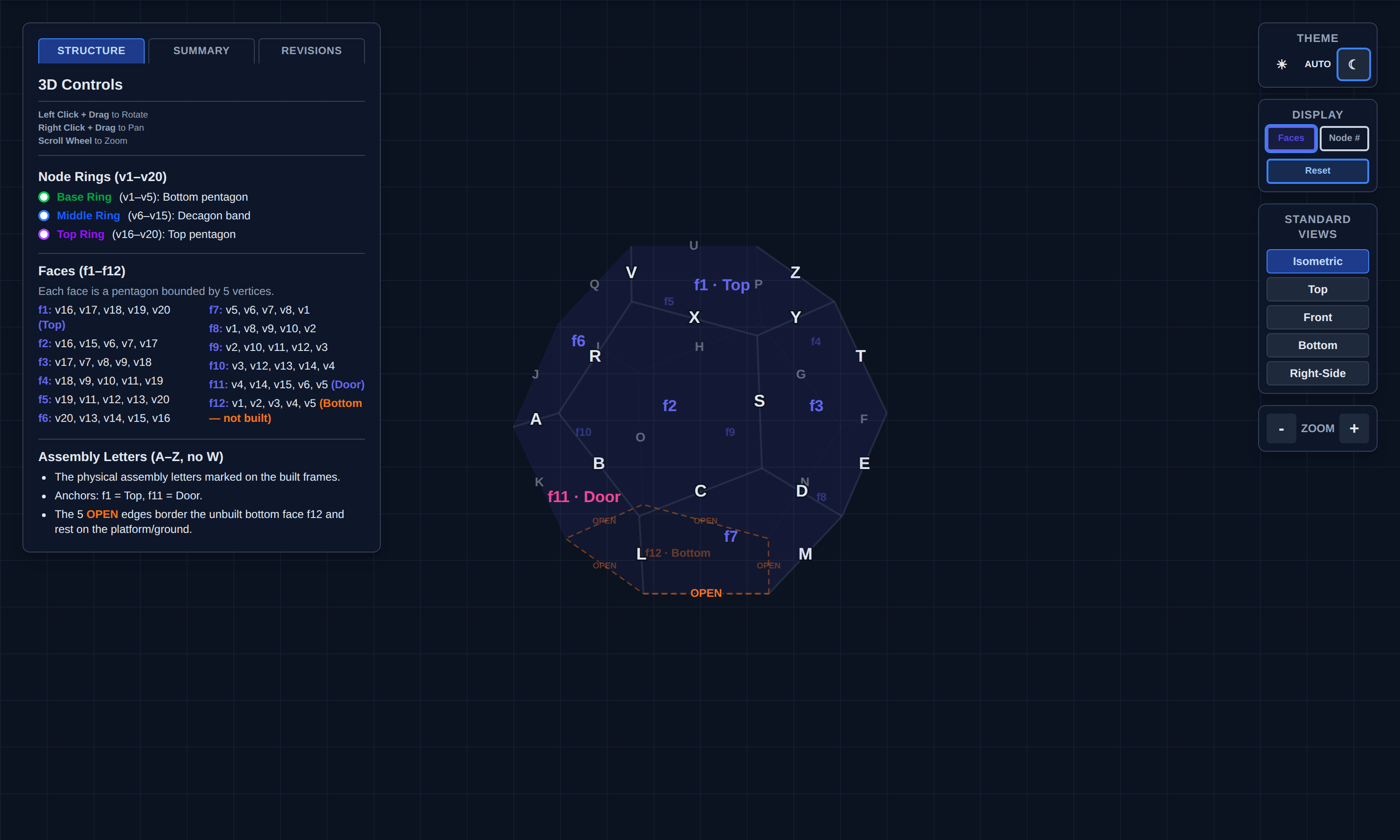 Assembly letters on the 30 edges,
 f1 · Top, f11 · Door, and the 5 dashed OPEN base edges. Snapshot of NaoDec_3D_Structure_Framework_Rev1.0.html (isometric, dark theme).
2.1 Pentagon Panel
Purpose: build the 11 wooden-frame + stretched-fabric pentagon panels.
2.1.1 How to Build the Panel?
Inputs needed (not yet specified):
- Frame material and section size
- Corner joinery method (how the 5 frame members meet at each pentagon corner)
- Fabric type and how it's stretched/attached to the frame
- Fastener spec
- Finished pentagon edge length and per-panel weight
Whatever the build method, every panel needs its assembly letters transferred onto the frame at each edge, per NaoDec_Face_Edge_Marking_Rev1.0.html (or the interactive variant), and its hinge halves fitted at 2 positions per lettered edge (see 2.2.1) — ideally on the bench, not on the ladder.
2.1.1.1 Side and Ceiling
The build method splits into Side and Ceiling variants:
- Side covers the 9 wall faces (
f2–f10— lower ringf7–f10and upper ringf2–f6minus the door). - Ceiling is
f1— the top, opposite the unbuilt bottom. - Not yet covered by this split: the door (
f11), which needs to open or be removable — arguably a third build variant. Also not addressed: how the frame confirms the bottom (f12) stays unbuilt/open at the platform interface.
(TBD — the actual build steps, materials, and what specifically differs between Side and Ceiling panels are pending the author's input.)
2.2 Panel Installation
Reference geometry: NaoDec_3D_Structure_Framework_Rev1.0.html (or the snapshots offline).
2.2.1 Hinged pairs — how panels attach
Every lettered edge gets 2 hinges; matching letters join. Only the 5 ground-resting edges have no hinges. The hinges are the panel-to-panel fastener — no separate bolts/clamps are specified. A hinge allows the pair to fold during handling; once the last panel closes the solid, the geometry itself locks every dihedral at ≈ 116.57° and the assembly becomes rigid.
Pre-build on the bench: 5 hinged pairs + 1 single panel (the door):
| Pair | Faces | Hinge joint | Hinge edge (vertices) | Section |
|---|---|---|---|---|
| 1 | f7 + f8 | M | v1–v8 | Lower |
| 2 | f9 + f10 | O | v3–v12 | Lower |
| 3 | f2 + f6 | R | v15–v16 | Upper |
| 4 | f3 + f4 | T | v9–v18 | Upper |
| 5 | f1 + f5 | U | v19–v20 | Ceiling + back wall |
| — | f11 (Door) | single panel | — | Lower |
The five pairs + door cover all 11 built faces exactly once. Note f5 is an upper-ring wall: pair 5 is "the ceiling and the wall it hinges to," not two ceiling panels.
The remaining 20 lettered joints are hinged on site during erection (2 hinges each, matching letters). Joint edges are crowded: 2 hinges + an internal LED strip (Step 4) + on joint M also speaker M (Step 5) + an external edge cover (Step 7) all share the same edge — see Open Items.
2.2.2 Erection sequence
- Lower section: stand pair f7-f8, pair f9-f10, and the door f11 on their ground edges (per the landing map in 2.2.3) and hinge the adjacent lower joints (L, N, K — matching letters).
- Upper section: lift pair f2-f6 and pair f3-f4 onto the lower ring; hinge every letter that meets (C, D, E, F, G, H, I, J, A, B, S).
- Close with pair f1-f5: the last lift places the 5th upper wall (
f5) and the ceiling (f1) together; hinge the remaining letters (P, Q, V, X, Y, Z). Closing this pair locks the whole solid rigid.
⚠ Until Phase 2 ties them together, the lower panels lean inward at ~116.57° and are not self-supporting — temporary bracing/props are required (spec TBD, see Open Items). The f1-f5 pair is the heaviest, highest lift; rigging method TBD.
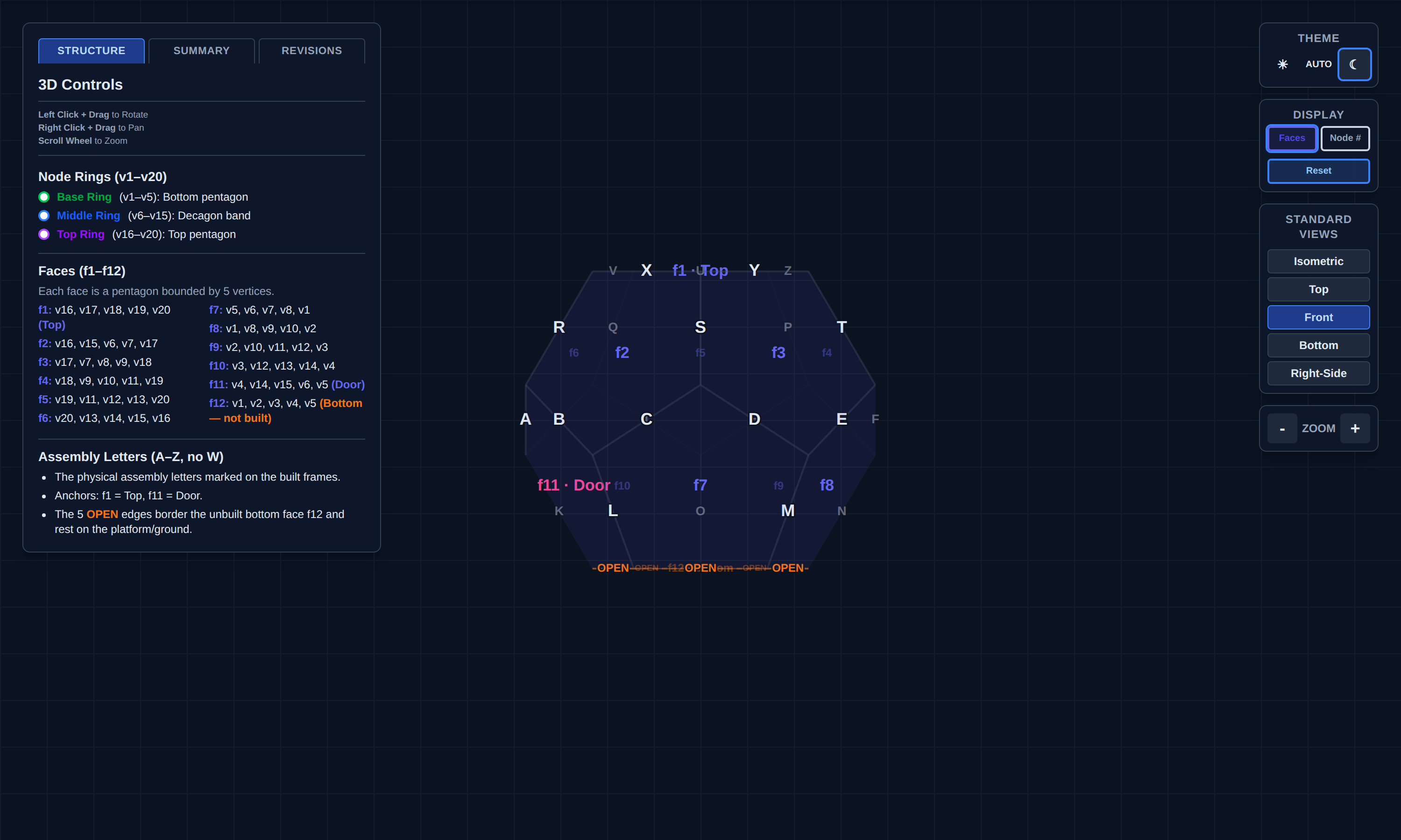 Front standard view — useful when checking letter positions phase by phase. Snapshot of
 NaoDec_3D_Structure_Framework_Rev1.0.html.
2.2.3 Base placement & registration
The 5 unlettered ground edges land on the platform as:
| Ground edge | Belongs to face |
|---|---|
| v5–v1 | f7 |
| v1–v2 | f8 |
| v2–v3 | f9 |
| v3–v4 | f10 |
| v4–v5 | f11 (Door) |
- The chair faces v1 (Step 6), and the controller unit sits outside, ~2–3 m from v1 (decision 1). The door edge (v4–v5) ends up behind-left of the seated occupant.
- Mark the platform before erecting anything: v1's corner position and the 5 ground-edge lines. One face of rotation error ruins every left/right instruction in Steps 3–9. Registration-mark method TBD.
- Which real-world direction v1 faces on site is an open item (index, Open Items #3).
Cross-References
NaoDec_Face_Edge_Marking_Rev1.0.html/ interactive — per-face letter diagramsNaoDec_3D_Structure_Framework_Rev1.0.html— 3D geometry with lettersPaint_Comparison_Maxzo_RustTech_vs_JBP_SmartGlaze.md— coating comparison, if panel frames get painted (still unplaced in the sequence)
Safety
- Unbraced lower ring: five inward-leaning panels + a door panel are unstable until the upper ring closes — keep crew clear of fall lines, brace each phase.
- Door egress: the door is the occupant's only exit (the bottom opening sits under the riser). Whatever mechanism 2.2's open item settles on must be operable from inside.
- The erected frame stands over the occupant; no frame load rating exists yet (see Step 1 Safety for the platform side).
Release Gate
| Gate | Required Result |
|---|---|
| 11 panels built | Frame + fabric complete, letters marked, hinge halves fitted per 2.2.1 |
| 5 pairs + door pre-built | Pair hinges (M, O, R, T, U) fold freely and seat at the dihedral |
| Base registered | Ground edges on the platform marks; v1 corner where planned |
| All 25 joints hinged | 2 hinges per joint, matching letters verified |
| Door | Operable from inside and outside (mechanism per Open Item #1) |
| Ground edges | Hinge-free, seated on the platform |
Open Items
- Door mechanism — with all four of its lettered edges hinged (A, B, K, L), how does
f11open? Designate a swing edge + lift-off/removable-pin hinges on the other three, or make the whole panel removable. Affects Step 7 (covers on door edges) and egress. - Hinge spec — type, size, load rating, removable-pin or fixed, corrosion finish: TBD. 50 hinges + spares.
- Temporary bracing for Phase 1/2 — props, clamps, crew count: TBD.
- Site orientation of v1 + platform registration-mark method (2.2.3).
- Hardware sharing the joint edges — 2 hinges + internal LED strip + (joint M) speaker + external cover per edge; a per-edge layout that keeps them from colliding is TBD.
- Panel construction specifics (2.1) — materials, joinery, fabric, fasteners, dimensions, weight.
- Side vs. Ceiling build differences (2.1.1.1) — plus the door as a likely third variant.
- Painting/finishing — the paint comparison doc exists but no step schedules painting.